You may remember this post from a while back. I’d got myself a Wii Motion Plus and was playing about with getting reading from it onto my PC.
Well, the reason I was doing that was that I wanted to build a quadrotor.
I put in on the back burner for a while after that, but eventually I bought a microcontroller – an LPC2103 on an Olimex header board.
A bit of hacky soldering later, and it looked like this:

(The blue PCB is a UART level shifter that I borrowed)
I put some work into recreating the same cube on the screen but this time with the integration of the gyro readings and thus the orientation estimate calculated by the microcontroller rather than the PC.
That work, specifically the I2C driver, inspired me to write a poem.
After getting that working I bought a Wii Nunchuck. That contains a 3-axis accelerometer and daisy-chains off the Wii Motion Plus. I then set to work on combining the readings from the Wii Motion Plus and the Nunchuck into a single orientation estimate.
After trying to get my head around applying Kalman filters to orientation estimation I eventually settled on the popular algorithm described in this paper.
When I had the two sensors working together to produce a single fused estimate of orientation, I started on the physical construction of the quadrotor.
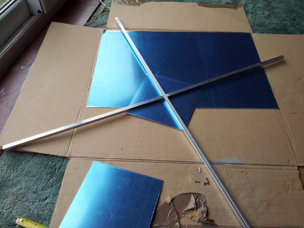
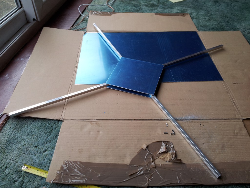
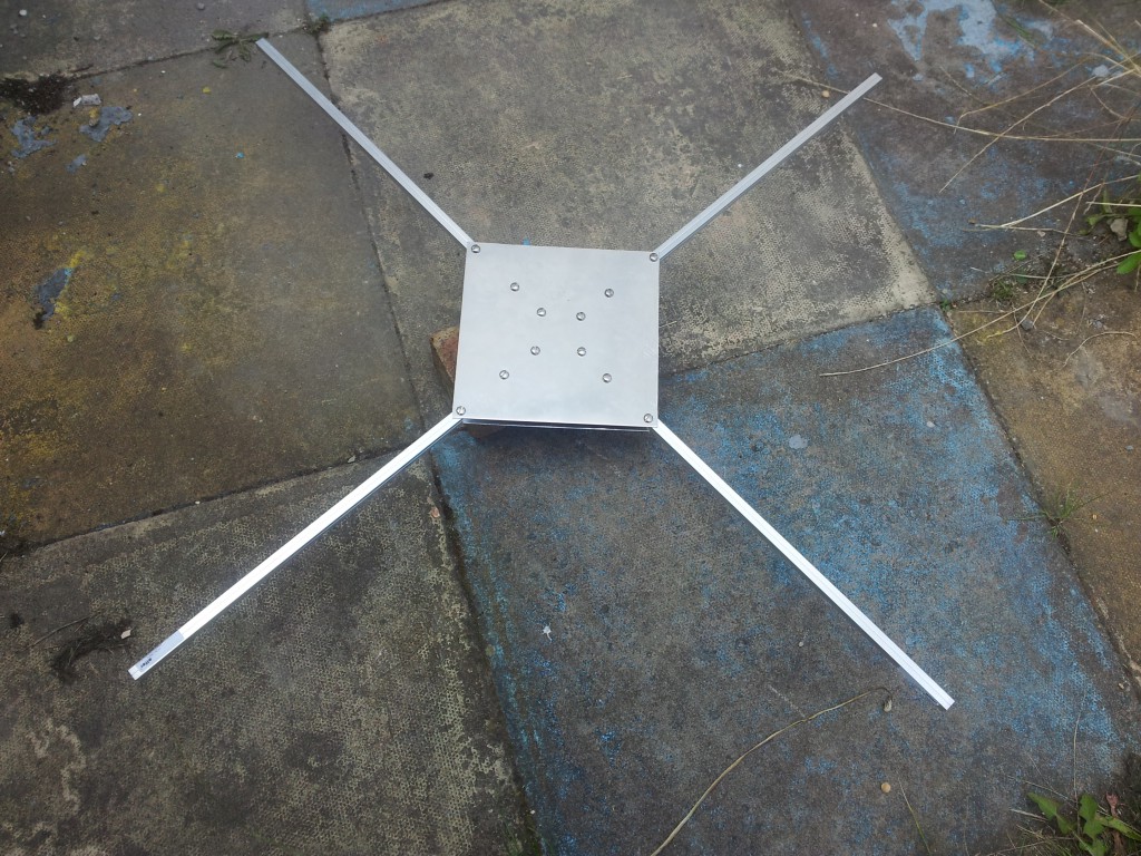
I bought two 1 metre long 11.5mm box section 1.5mm thick aluminium pieces and a sheet of 1.5mm thick aluminium to work with. I cut half way through in the centre of each piece so that they could fit together in a neat cross. I also cut out two 20cm square bits of aluminium.
I then drilled holes through the frame and put M5 bolts through it to hold it together.
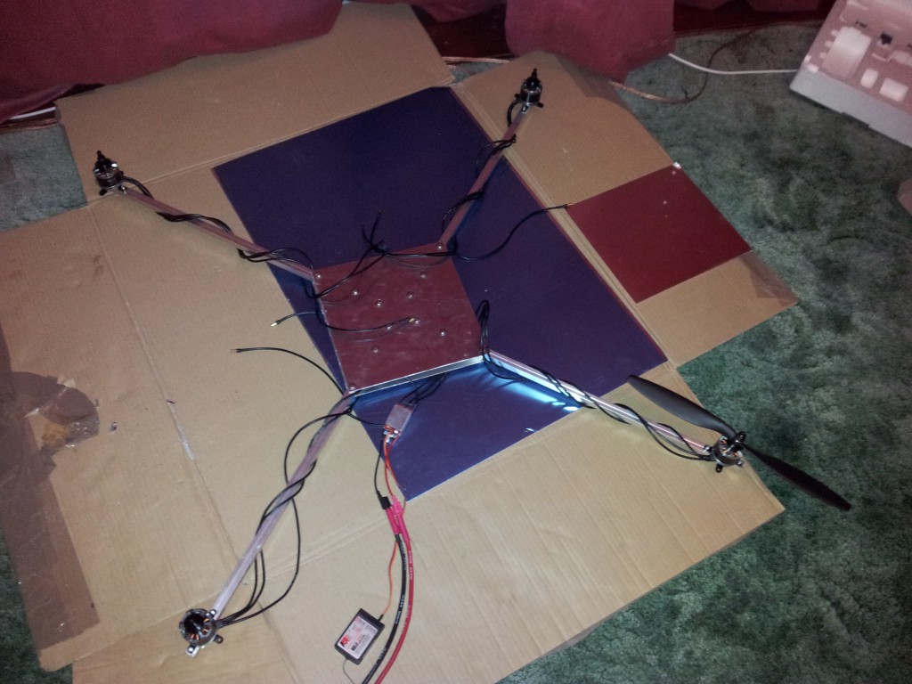
Then it was time for motors. I’d used eCalc to run various scenarios and help me choose motors, props, ESCs and a battery, and I settled on the MT2814-10 motor and the 30A ESC from the same manufacturer.
I drilled some smaller holes in the ends of the arms and mounted the motors with M3 bolts.
At this point I could connect a radio to it. I’d bought a FlySky 9X system and so I simply connected the throttle channel to one of the ESCs for testing.
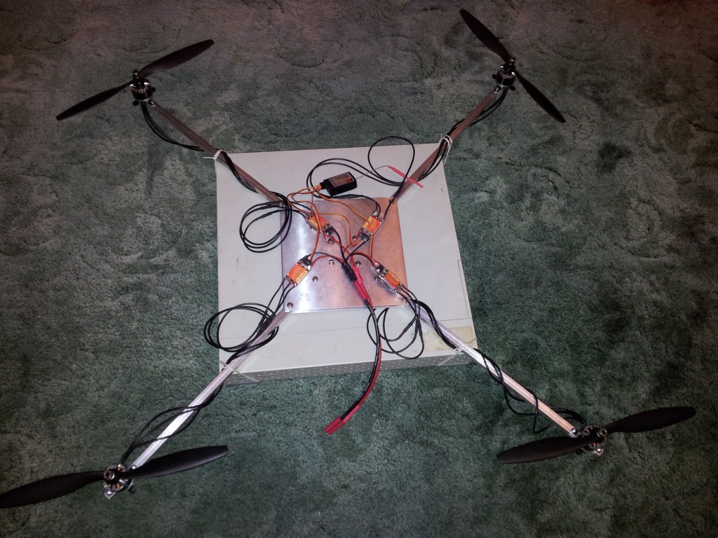
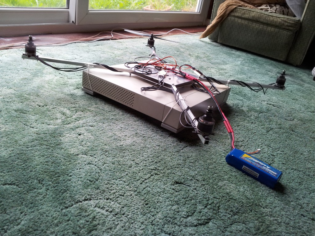
It was quite powerful. It needed actual effort to hold down and the arm was visibly bending under the thrust produced by the motor. So I tied it down to the biggest and heaviest object of a suitable shape which I could find – a SPARCstation 1+.
I then connected up all of the ESCs to radio channels to try it out with all of the motors going.
Even all four of these immensely powerful motors were not able to lift the weight of a SPARCstation 1+ off the ground. However, unbalanced thrust was certainly capable of tilting it. With three motors running it got one side off the ground.
With only two motors running, things were worse. I had to kill the power quickly as it was really lifting one side off the ground. I didn’t take a photo of that.
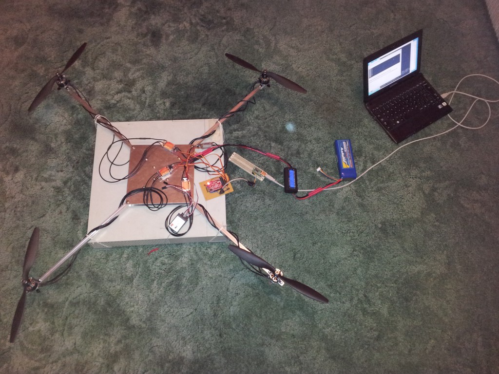
At this point I went back to the microcontroller and started writing some more code. Code to output PWM to the ESCs. I also soldered some headers onto some perfboard to make a suitable breakout into which I could plug in all of the bits and pieces on the quadrotor.
I could then give it rudimentary commands from the laptop. I attached a power meter and measured the power taken with all four motors on full power. With a fairly full battery, this was 1.5kW. The battery is a 5000mAh 4 cell lithium polymer battery rated at 20C/30C discharge.
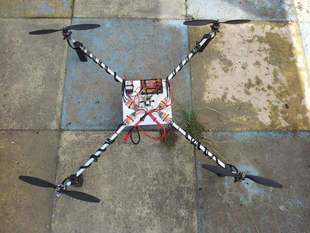
I wrote some code to time incoming PWM signals from the radio. Then I finished off the physical build. I drilled holes in the top surface to put cable ties through, allowing all of the components to be tied down. I glued the Wii Motion Plus to the Nunchuck with some spare nuts as spacers and tied down the whole assembly onto the top surface with some plastic in between to aid mounting. I made a battery compartment out of a couple of bits of bent aluminium and some plastic, velcro and a shoelace.
I then made the world’s worst quadrotor feet out of some bits of plastic left over from fixing my shower. I cut lengths of this plastic corner material and stuck two together using electrical tape to make a square section. I then cut out notches from the corners to make space for the quadrotor arms and taped them to the underneath of the arms as feet. The electrical tape didn’t last long for this, and so the attachment to the arms was replaced by gaffer tape not long afterwards.
Including battery, the whole airborne weight comes in at just under 2.4kg.
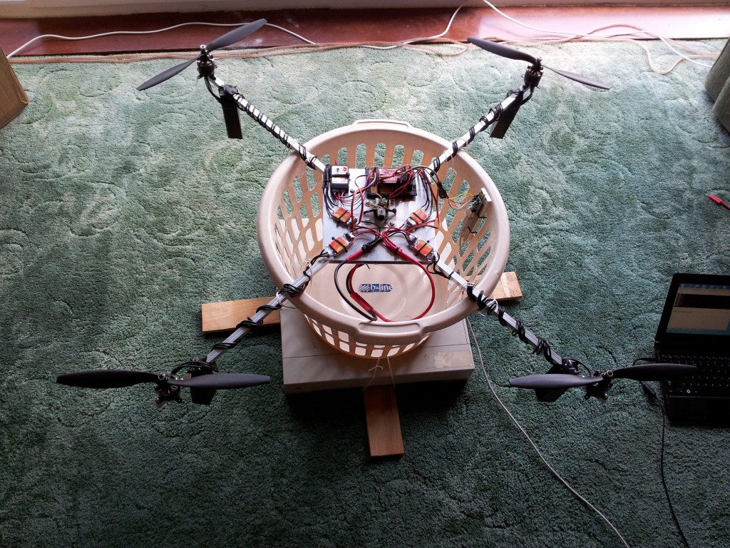
I constructed another tethering rig using the SPARCstation 1+, some bits of wood to stop it tipping over, and a laundry basket. I hoped that it would provide enough movement for the quadrotor for PID tuning.
But that didn’t really work. I ended up doing most of the tuning by holding it very carefully in my hands.
I used PID control in the pitch, roll and yaw axes. Many places suggest beginning the tuning process by setting I and D to zero and finding the right value of P. That really doesn’t work with this system. Either P is so high that it wildly oscillates, and the control response is too slow, or P is so low that it is chaotic due to the inherent instability of the system.
It turns out to be necessary to start by setting the D term. It changed the effective inertia of the system to the point that it was possible to observe the effect of the P term. And the physical feeling really surprised me – just by changing a number in software, suddenly it felt like an object many times more massive. I played a bit with P and I after this and got some values that worked. They’re almost certainly not optimal, but they’re good enough for now.
And then it was flying.
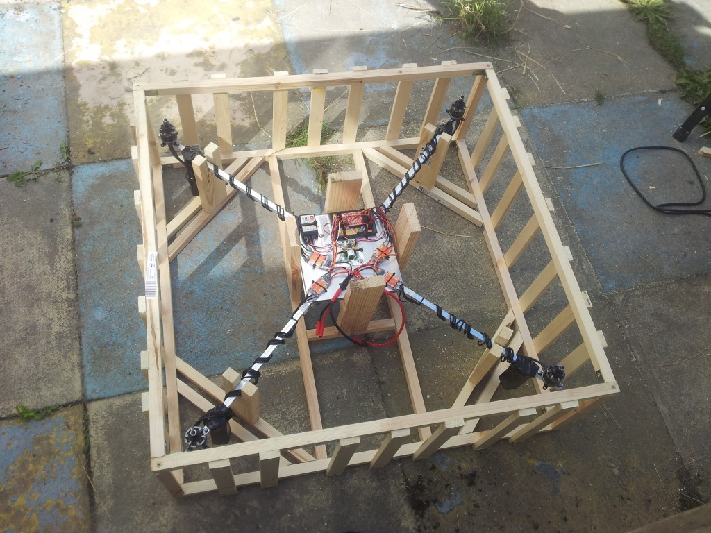
I wanted to take it to EMF, the UK’s first hacker camp. I’d just about managed to get it flying the day before the event started and so I set about solving the problem of how to get it there. It’s substantially bigger than many other quadrotors and isn’t really designed to be packed down. So I built a custom shipping crate.
At EMF there was a slightly larger flying area. I got some practice in over the weekend as I’m still a total beginner when it comes to flying RC aircraft.
Then somebody convinced me to attach my camera phone with gaffer tape.
Later on somebody came along with some electroluminescent wire and we strapped it on to enable night flying. We also ended up with a picoprojector on board, projecting the EMF logo onto the ground. It wasn’t really bright enough to get a clear picture on the grass, but it was fun trying.
We then discovered we could stop the EL wire from flashing, which made it a little easier to fly. And somebody came along with a Go Pro HD camera. We did a couple of flights with the camera pointing straight down but they weren’t really all that interesting. Then we strapped one of the IP cameras to one of the arms and got some nice footage with one rotor in the foreground and the lights of the camp in the background.
I am of course really excited to have this flying, but there are a few issues with it that I’ve discovered so far. I can’t blame all of them on my novice piloting skills.
I noticed a tendency to oscillate when compensating for wind, especially when trying to descend. I’m putting this down to the PID values needing a bit more tuning.
I really need telemetry data in order to address that properly, so I will have to think of a good way to record data in-flight.
Also I noticed once or twice that it lots its idea of orientation after some fairly aggressive manouvres. It did eventually drift back towards the correct attitude but it’s still a problem that needs addressing. Telemetry data would help with that too.
And the feet. Of course, the feet. They break off or partially break off on anything other than a perfectly vertical and smooth landing. I’m claiming that this is deliberate and that they are sacrificial protection, honest! However, I would like something a bit more durable.
So what next? Well, the obvious choices are telemetry, pressure sensor for altitude stabilisation, a magnetometer for an absolute yaw reference, and GPS for position hold / reporting. And then also waypoint-based autopilot and return to base / autoland functionality.
Oh, and, learning to fly it.
The firmware is available in my monotone repository, in the org.coolfactor.quadrotor branch. See here for licensing details.

7 Responses to Quadrotor